Technology brief of low flow anesthesia
First, it is good to remember that clinical skills and expertise are always important. To work safely, you have to remember the basic underlying pharmacological and physiologic principles. Understanding how gas concentrations behave in a circle system and how they depend on different fresh gas flows (FGF) is important. The lower the FGF, the more important this basic knowledge is. As always in anesthesia practice, the clinician needs to know possible risks versus benefits of a certain technique. Particularly in low and minimal flow anesthesia, the clinician has to understand the importance of monitoring of ventilation and the measurement of gas concentrations from the Y-piece.
Technical requirements
In low flow anesthesia, there are a few technical requirements which will be briefly explained here. Typically, they are rather generic and more or less independent of anesthesia machines used.
- Circle rebreathing system with CO2 absorption.
- Accurate flow meters for adjustment of fresh gas flows below 1.0 L/min.
- Accurate vaporizers, capable of reliably delivering volatile anesthetic agent concentrations with fresh gas flows below 1.0 L/min.
- There needs to be a gas-tight breathing system. Recommended test leakage should be below 150 mL/min at 30 cmH2O test pressure. Typically, ascending bellows not rising up to the top of the bellows chamber may indicate breathing system leakage. Another indication of circuit leak could be that the peak airway pressure LOW ALARM would become active. In addition, if the spirometry loops displayed on the monitor screen not closing correctly, that may also indicate a leak.
- The breathing system should have minimal internal volume and a minimum number of components and connections.
- Continuous gas monitoring should be employed. In fact, inspiratory and expiratory gas concentrations should be measured breath by breath. From the clinical standpoint, the measurement of expiratory gas concentrations close to the Y-piece is of crucial importance. That information is essential in controlling the patient ’s alveolar gas concentrations, whereas inspiratory gas concentrations reflect the adequacy of gas concentrations delivered into the breathing circuit.
In addition to the above listed recommendations, monitoring of ventilation should always be employed. End-tidal CO2 measurement will give that information, and helps to controll the patient’s alveolar ventilation. For controlling breathing system volumes and lung mechanics of the patient, additional information can be obtained by monitoring airway pressures, breathing volumes, and spirometry loops.
What is good to know about the components of the circle system?
The circle system enables rebreathing of gases in the circle and allows use of variable fresh gas flows. Depending on the FGF delivered, the circle system can function in the different ways listed in the Educational Support tutorial, “What and why in low flow anesthesia”.
List of components of a circle system will follow
- Fresh gas inlet
- Inspiratory limb with one-way valve
- Expiratory limb with one-way valve
- Absorber for carbon dioxide removal
- Volume reservoir for positive pressure ventilation, either manual bag or ventilator bellows may be connected here.
- Overflow valve for scavenging waste gases
- Patient Y-piece and spirometry flow sensor and gas sampler
- Bacterial filter may be added here
What is the chemical process of CO2 absorption with the soda lime?
In the circle rebreathing system, the CO2 absorber removes carbon dioxide from the inhaled gas. The CO2 absorption is a chemical reaction which, in addition to CO2 removal, produces heat and moisture.
CO2 +H2O <=> H2CO3
H2CO3 +2NaOH --> Na2CO3 +2H2O
H2CO3 +2KOH --> K2CO3 +2H2O
Na2CO3 +Ca(OH)2 --> 2NaOH +CaCO3
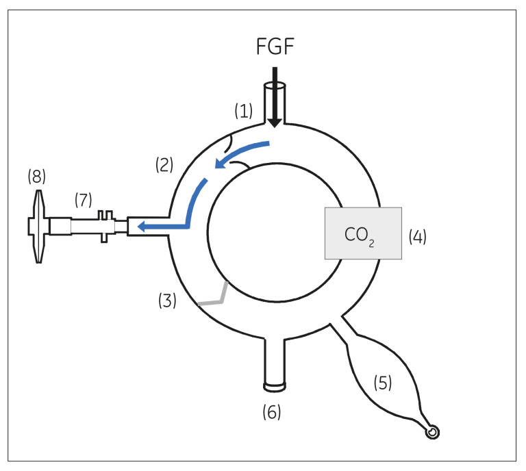
Figure: Inspiratory phase.
During inspiration, the expiratory valve is closed and inspiratory gases flow through the inspiratory one-way valve to the patient.
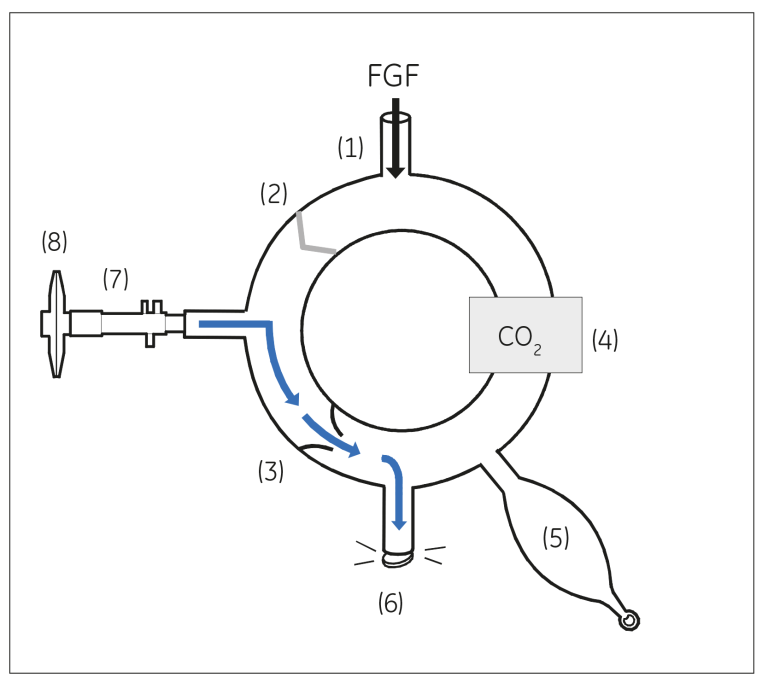
Figure: Expiratory phase
During expiration, the inspiratory valve is closed and expiratory gases flow through the expiratory one-way valve to the breathing bag or bellows and then to the overflow valve.
How long can I use the CO2 absorber without replacement?
The absorption capacity of the absorber is based on the minute ventilation of the patient (adjusted by patient’s CO2 production), the volume of the CO2 absorber, and the selected fresh gas flow rate.
The lower the fresh gas flow, the more the gas recycles in the circle and the more CO2 the absorber then removes. Hence, the lower the fresh gas flow, the shorter the duration of time the absorber canister can be used.
So, when should the absorber be changed?
The time to change the absorber is when there is a clear increase in the measured Fi CO2 values (lower arrow on the trend curve below, indicates rise of end tidal CO2) and without significant changes in the patient’s ventilator settings.
Usually, there is also an indicator color in the soda lime. When the color of the soda lime changes permanently that indicates the time to change the absorber. One point to keep in mind is that after some time, that color change may fade away. Hence, it is better to change the absorber by yourself instead of leaving it overnight, as people the next day might not be aware of the information about the capacity of the absorber.
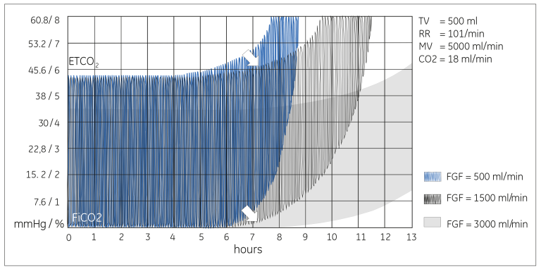
Figure: Laboratory test results showing how different fresh gas flows affect the duration of usability of the Datex-Ohmeda Compact Block absorber, which has a volume of 500 mL.
If low FGF of 500 mL/min is used, the absorber has a capacity of close to seven hours. However, with a FGF of 3.0 L/min, the absorber can be used for more than 10 hours.
Additional resources
For white papers, guides and other instructive materials about GE Healthcare’s clinical measurements, technologies and applications, please visit http://clinicalview.gehealthcare.com/
JB67912XX

