What is ST segment analysis?
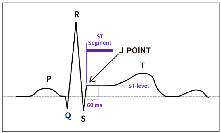
The sequential electrical activation of the heart muscle results in P-, QRS- and T-waves in the ECG. The P-wave represents atrial depolarization, the QRS-complex represents ventricular depolarization, and the T-wave represents ventricular repolarization. The ST segment, the phase between the ventricular depolarization and repolarization, is usually isoelectric and slightly slanted upwards.
In coronary artery disease the blood flow to the heart muscle may be compromised. If oxygen delivery is not sufficient, ischemia results in the myocardium. The ischemic tissue cannot maintain the membrane potential. This is seen by displacement of the ST segment: downwards in subendocardial injury and upwards in subepicardial injury. The larger the ischemic area, the greater this deviation. The most commonly accepted criteria for evidence of myocardial ischemia is ST segment deviation greater than 1 mm (0.1 mV).1
Why 12-lead ST monitoring?
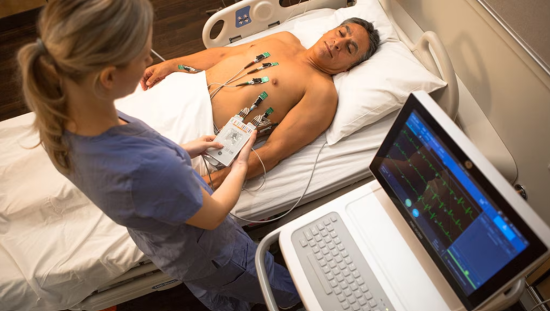
Early detection of ischemia can help in the institution of timely lifesaving intervention. Persistent ST segment elevation is a sign of acute myocardial injury: the more leads involved, the more detail can be provided about the injury.
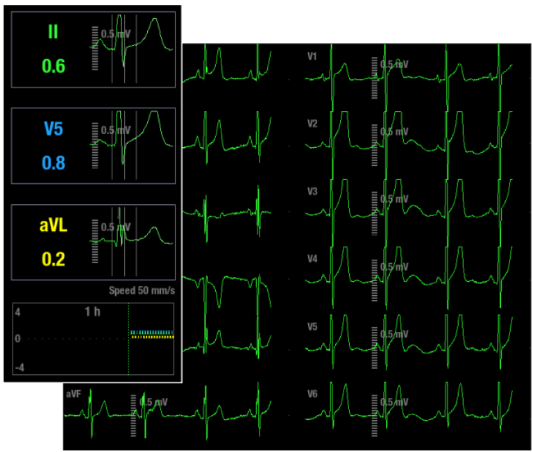
ST changes in different leads reflect the location of the ischemic area. A method of increasing the sensitivity in order to detect ischemic events is to add more ECG leads. If lead V5 is used alone the sensitivity is found to be 75%. But if leads V4 and V5 are used concurrently, the sensitivity increases up to 90%. The conventional combination of leads II and V5 give a sensitivity of 80%. However, if leads II, V4 and V5 are combined, the sensitivity increases to 96%. Sensitivity of close to 100% is achieved if leads V2 and V3 are added to the above given lead combination.2
NOTE: ST segment changes may also be affected by such factors as some drugs or metabolic and conduction disturbances.
NOTE: The significance of the ST segment changes needs to be determined by a physician.
How is the ST segment analyzed?
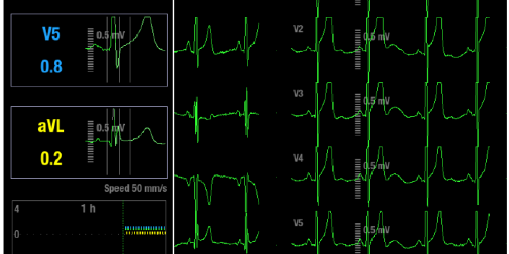
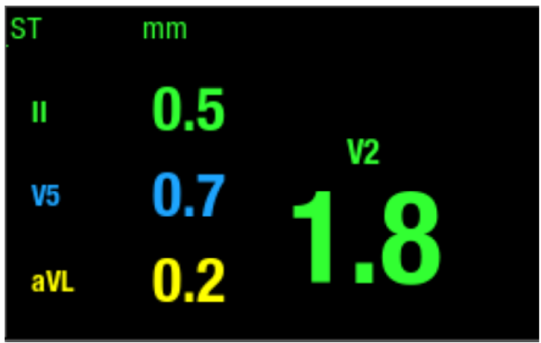
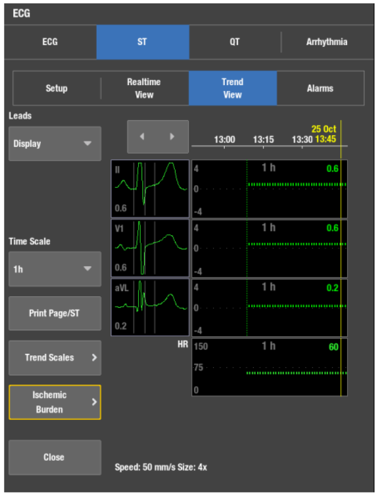
The ST parameter window shows three user selectable ST leads. The fourth ST value shows the largest absolute ST lead of all monitored leads. The ST segment begins at the point where the QRS ends (J-point). Typically ST changes are measured at 60 ms or 80 ms after J-point. For monitoring purposes it is important that the measurement point is accurate to obtain a reliable trend of ST changes.
The sophisticated algorithms in GE HealthCare monitors search for the J and isoelectric (ISO) points. The ISO point is a point on the isoelectric line and is considered the baseline voltage of ECG. The system learns the ECG and stores the reference QRST complex. The algorithm sets the ISO and J points automatically. These points can also be adjusted manually. The QRS analysis classifies each beat by using several criteria and rejects distorted complexes from the ST calculation.
ST is analyzed for all measured leads. With a 10-lead leadwire set GE HealthCare monitors analyze and trend the ST segment changes continuously for 12 leads. With a 6-lead leadwire set continuous ST segment analysis and trending are done for eight leads, or for 12-leads if the 12RL™ algorithm is in use. (Please consult “12RL Reconstructed 12 lead ECG Quick Guide” or the monitor’s manual for details.) With a 5-lead leadwire set analysis and trending are done for seven leads, and with a 3-lead leadwire set analysis and trending are done for one lead.
The ST parameter window shows three user selectable ST leads. The fourth ST value shows the largest absolute ST lead of all monitored leads. The user can also choose all leads to be shown as an alternative to ST number field. The “All leads” option shows ST values for all available ECG leads. This may help the clinician to notice if ischemia is spreading to new areas.
Tracking ischemic changes in the QRST complex
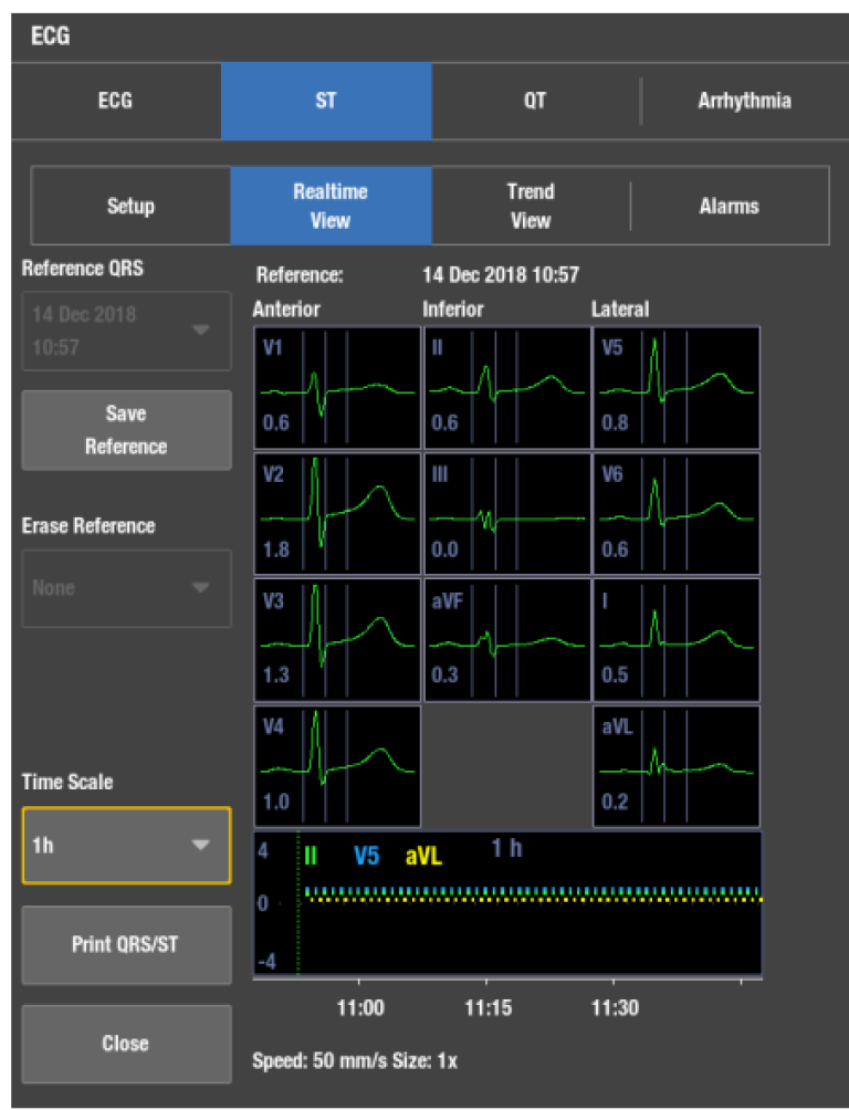
Upon initiation the monitor learns the reference ST values. The monitor will analyze and store the reference QRST complexes of all leads, which can be easily compared to the following complexes. It is important to have the capability to store and interchange reference QRST complexes. This allows the clinician to see the effect of treatment on the patient.
It is possible to store and select up to seven reference QRST complexes during monitoring. The clinician may review the ST changes during each course of therapy (e.g. through the entire thrombolysis and revascularization procedures).
In addition to trending ST values, the GE HealthCare's solution is also capable of trending the shape of the QRST complex. QRST complexes are automatically saved for all leads every 10 minutes. These complexes can be reviewed by simply moving the cursor on the ST trends. Furthermore, the user may print the stored complexes to track the progress of the ST level over a selected time period.
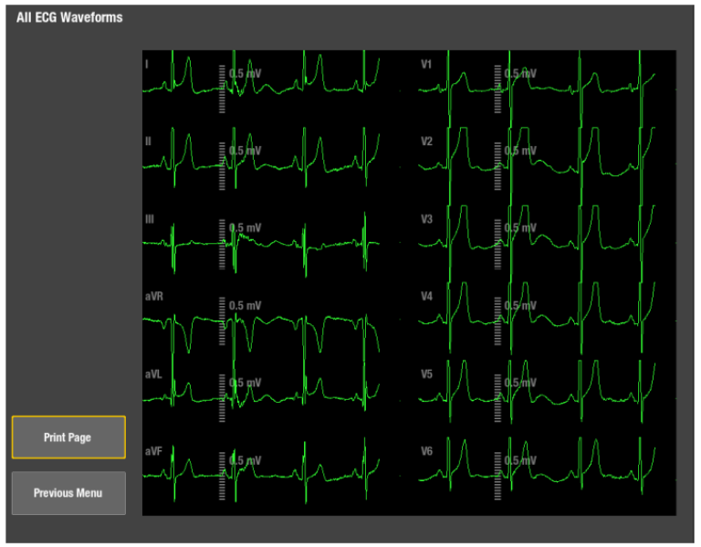
Localizing the ischemic area
Localizing the area of ischemia on the 12-lead ECG is a clinical necessity. The leads of the 12-lead ECG are grouped according to the regions of heart they view. One criterion for identifying myocardial ischemia is ST elevation of 1 mm or more observed in two contiguous ECG leads.3
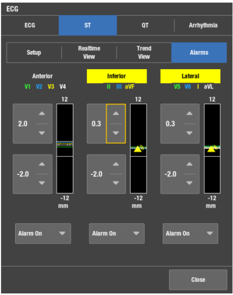
The GE HealthCare's solution provides viewing, printing and alarm setting capabilities for the leads shown. Lead grouping, combined with clear, concise trend analysis, allows for accurate estimation of patient ischemic status. The ischemic burden view is a graphical way to show ischemic changes by lead groups.
Ischemic burden
Instead of a single ST value, the duration and trend of the ischemic events are considered to provide the most valuable information while assessing the severity of cardiac ischemia.
In the GE HealthCare's patient monitoring solution, the sophisticated ischemic burden display gives valuable information about the development of ischemia. In the ST trend screen the user may select the thresholds over which the monitored ST levels should not rise. If the monitor detects ST levels over the threshold, the area will be shaded by a specific color. This allows easy and accurate visualization in the duration of ischemic events.
Practical aspects of ST segment monitoring
Other factors affecting the ST segment
Prinzmetal’s angina is a temporary, reversible coronary artery spasm, which may or may not be associated with chest pain. It is indicated in the ECG as ST elevation, which resolves in minutes. Acute pulmonary embolism may be associated with ST elevation in leads monitoring the right side of the heart. In pericarditis ST elevation is frequently seen, but is diffuse and involves multiple leads.
Filtering
The ST segment changes represent the low frequency changes in the ECG. The filter setting choices are diagnostic, monitoring, moderate or maximum filter. ST calculations are not affected by the filter settings, but only the waveforms on the monitor screen or on a printed strip may be affected.
Pacemaker patients
The ST segment of paced beats may not be diagnostic for ischemia or infarct. For ST level estimation Ek-Pro algorithm uses beats with normal morphologies. It should be noted there are differences in functionality between the previous generation GE HealthCare patient monitors. Please consult the appropriate user’s manual for details.
Additional resources
For white papers, guides and other instructive materials about GE HealthCare’s clinical measurements, technologies and applications, please visit clinicalview.gehealthcare.com
References
- Barill, Tracy., An ECG Primer. Nursecom Educational Technologies, 87, (2003).
- London MJ: “Intraoperative Myocardial Ischemia: Localization by Continuous 12-Lead Electrocardiography,” Anesthesiology 69, 232-41 (1988).
- Barill, Tracy., An ECG Primer. Nursecom Educational Technologies, 87, (2003).

