

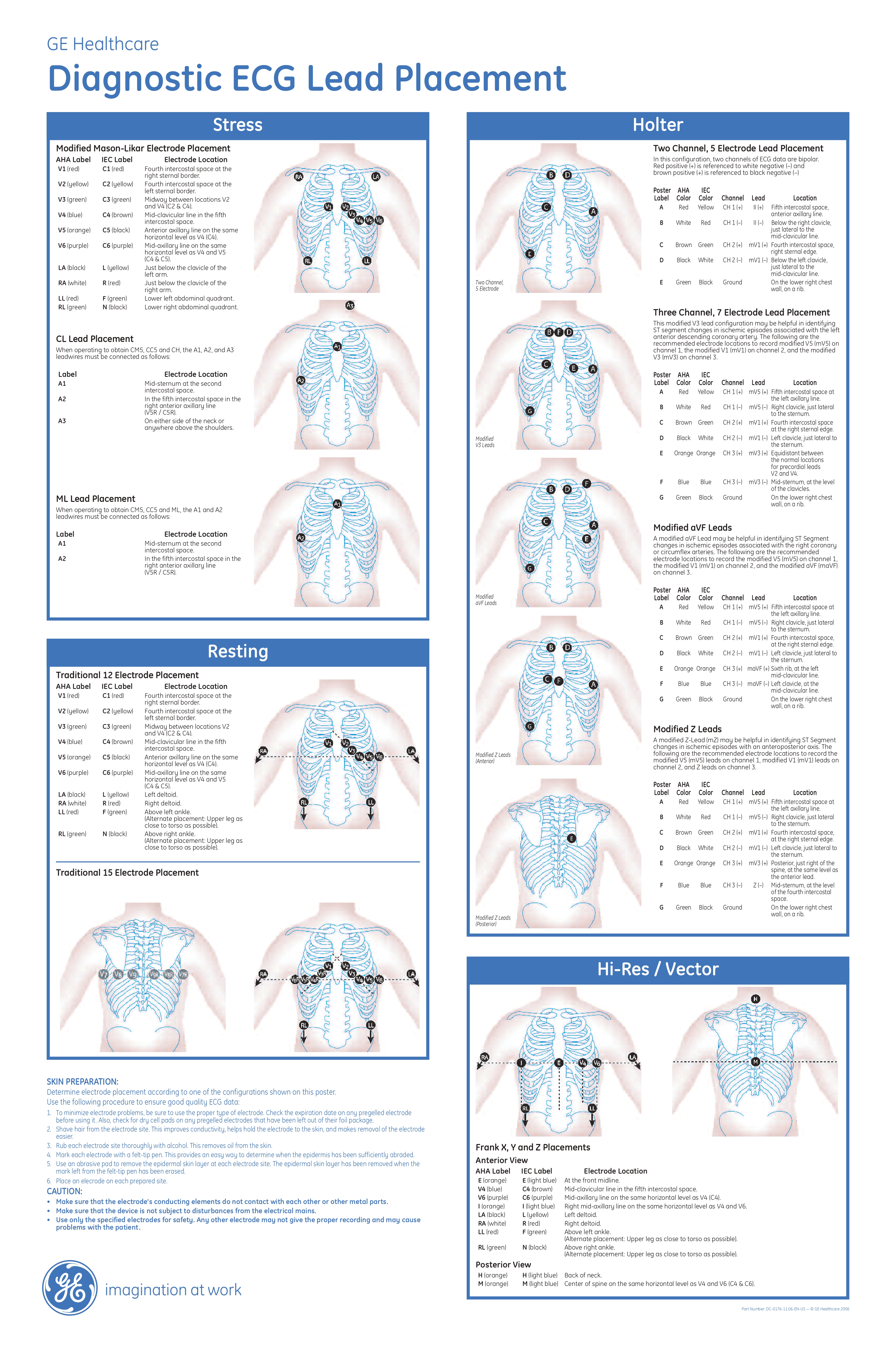
Stress
Modified Mason-Likar Electrode Placement
AHA Label - IEC Label - Electrode Location
V1 (red)- C1 (red) - Fourth intercostal space at the right sternal border
V2 (yellow) - C2 (yellow) - Fourth intercostal space at the left sternal border.
V3 (green) - C3 (green) - Midway between locations V2 and V4 (C2 & C4).
V4 (blue) - C4 (brown) - Mid-clavicular line in the fifth intercostal space.
V5 (orange) - C5 (black) - Anterior axillary line on the same horizontal level as V4 (C4).
V6 (purple) - C6 (purple) - Mid-axillary line on the same horizontal level as V4 and V5 (C4 & C5).
LA (black) - L (yellow) - Just below the clavicle of the left arm.
RA (white) - R (red) - Just below the clavicle of the right arm.
LL (red) - F (green) - Lower left abdominal quadrant.
RL (green) - N (black) - Lower right abdominal quadrant.
CL Lead Placement
When operating to obtain CM5, CC5 and CH, the A1, A2, and A3 leadwires must be connected as follows:
Label - Electrode Location
A1 - Mid-sternum at the second intercostal space.
A2 - In the fifth intercostal space in the right anterior axillary line (V5R / C5R).
A3 - On either side of the neck or anywhere above the shoulders.
ML Lead Placement
When operating to obtain CM5, CC5 and ML, the A1 and A2 leadwires must be connected as follows:
Label - Electrode Location
A1 - Mid-sternum at the second intercostal space.
A2 - In the fifth intercostal space in the right anterior axillary line (V5R / C5R).
Resting
Traditional 12 Electrode Placement
AHA Label - IEC Label Electrode - Location
V1 (red) - C1 (red) - Fourth intercostal space at the right sternal border.
V2 (yellow) - C2 (yellow) - Fourth intercostal space at the left sternal border.
V3 (green) - C3 (green) - Midway between locations V2 and V4 (C2 & C4).
V4 (blue) - C4 (brown) - Mid-clavicular line in the fifth intercostal space.
V5 (orange) - C5 (black) - Anterior axillary line on the same horizontal level as V4 (C4).
V6 (purple) - C6 (purple) - Mid-axillary line on the same horizontal level as V4 and V5 (C4 & C5).
LA (black) - L (yellow) - Left deltoid.
RA (white) - R (red) - Right deltoid.
LL (red) - F (green) - Above left ankle. (Alternate placement: Upper leg as close to torso as possible).
RL (green) - N (black) - Above right ankle. (Alternate placement: Upper leg as close to torso as possible).
Traditional 15 Electrode Placement
Holter
Two Channel, 5 Electrode Lead Placement
In this configuration, two channels of ECG data are bipolar. Red positive (+) is referenced to white negative (–) and brown positive (+) is referenced to black negative (–)
Poster - AHA - IEC
Label - Color - Color - Channel - Lead - Location
A - Red- Yellow - CH 1 (+) - II (+) - Fifth intercostal space, anterior axillary line.
B - White - Red - CH 1 (–) - II (–) - Below the right clavicle, just lateral to the mid-clavicular line.
C - Brown - Green - CH 2 (+) - mV1 (+) - Fourth intercostal space, right sternal edge.
D - Black - White - CH 2 (–) - mV1 (–) - Below the left clavicle, just lateral to the mid-clavicular line.
E - Green - Black - Ground - - - - On the lower right chest wall, on a rib.
Three Channel, 7 Electrode Lead Placement
This modified V3 lead configuration may be helpful in identifying ST segment changes in ischemic episodes associated with the left anterior descending coronary artery. The following are the recommended electrode locations to record modified V5 (mV5) on channel 1, the modified V1 (mV1) on channel 2, and the modified V3 (mV3) on channel 3.
Poster - AHA - IEC
Label - Color - Color - Channel - Lead - Location
A - Red - Yellow - CH 1 (+) - mV5 (+) - Fifth intercostal space at the left axillary line.
B - White - Red - CH 1 (–) - mV5 (–) - Right clavicle, just lateral to the sternum.
C - Brown - Green - CH 2 (+) - mV1 (+) - Fourth intercostal space at the right sternal edge.
D - Black - White - CH 2 (–) - mV1 (–) - Left clavicle, just lateral to the sternum.
E - Orange - Orange - CH 3 (+) - mV3 (+) - Equidistant between the normal locations for precordial leads V2 and V4.
F - Blue - Blue - CH 3 (–) - mV3 (–) - Mid-sternum, at the level of the clavicles.
G - Green - Black - Ground --- On the lower rig
Modified aVF Leads
A modified aVF Lead may be helpful in identifying ST Segment changes in ischemic episodes associated with the right coronary or circumflex arteries. The following are the recommended electrode locations to record the modified V5 (mV5) on channel 1, the modified V1 (mV1) on channel 2, and the modified aVF (maVF) on channel 3.
Poster - AHA - IEC
Label - Color - Color - Channel - Lead - Location
A - Red -Yellow - CH 1 (+) - mV5 (+) - Fifth intercostal space at the left axillary line.
B - White - Red - CH 1 (–) - mV5 (–) - Right clavicle, just lateral to the sternum.
C - Brown - Green - CH 2 (+) - mV1 (+) - Fourth intercostal space, at the right sternal edge.
D - Black - White - CH 2 (–) - mV1 (–) - Left clavicle, just lateral to the sternum.
E - Orange - Orange - CH 3 (+) - maVF (+) - Sixth rib, at the left mid-clavicular line.
F - Blue - Blue - CH 3 (–) - maVF (–) - Left clavicle, at the mid-clavicular line.
G - Green - Black - Ground - - - On the lower right chest wall, on a rib.
Modified Z Leads
A modified Z-Lead (mZ) may be helpful in identifying ST Segment changes in ischemic episodes with an anteroposterior axis. The following are the recommended electrode locations to record the modified V5 (mV5) leads on channel 1, modified V1 (mV1) leads on channel 2, and Z leads on channel 3.
Poster - AHA - IEC
Label - Color - Color - Channel - Lead - Location
A - Red - Yellow - CH 1 (+) - mV5 (+) - Fifth intercostal space at the left axillary line.
B - White - Red - CH 1 (–) - mV5 (–) - Right clavicle, just lateral to the sternum.
C - Brown - Green - CH 2 (+) - mV1 (+) - Fourth intercostal space, at the right sternal edge.
D - Black - White - CH 2 (–) - mV1 (–) - Left clavicle, just lateral to the sternum.
E - Orange - Orange - CH 3 (+) - mV3 (+) - Posterior, just right of the spine, at the same level as the anterior lead.
F - Blue - Blue - CH 3 (–) Z (–) Mid-sternum, at the level of the fourth intercostal space.
G - Green - Black - Ground - - - On the lower right chest wall, on a rib.
Hi-Res/ Vector
Frank X, Y and Z Placements
Anterior View
AHA Label - IEC Label - Electrode Location
E (orange) - E (light blue) - At the front midline.
V4 (blue) - C4 (brown) - Mid-clavicular line in the fifth intercostal space.
V6 (purple) - C6 (purple) - Mid-axillary line on the same horizontal level as V4 (C4).
I (orange) - I (light blue) - Right mid-axillary line on the same horizontal level as V4 and V6.
LA (black) - L (yellow) - Left deltoid.
RA (white) - R (red) - Right deltoid.
LL (red) - F (green) - Above left ankle. (Alternate placement: Upper leg as close to torso as possible).
RL (green) - N (black) - Above right ankle. (Alternate placement: Upper leg as close to torso as possible).
Posterior View
H (orange) - H (light blue) - Back of neck.
M (orange) - M (light blue) - Center of spine on the same horizontal level as V4 and V6 (C4 & C6).
Skin preparation
Determine electrode placement according to one of the configurations shown on this poster. Use the following procedure to ensure good quality ECG data:
- To minimize electrode problems, be sure to use the proper type of electrode. Check the expiration date on any pregelled electrode before using it. Also, check for dry cell pads on any pregelled electrodes that have been left out of their foil package.
- Shave hair from the electrode site. This improves conductivity, helps hold the electrode to the skin, and makes removal of the electrode easier.
- Rub each electrode site thoroughly with alcohol. This removes oil from the skin.
- Mark each electrode with a felt-tip pen. This provides an easy way to determine when the epidermis has been sufficiently abraded.
- Use an abrasive pad to remove the epidermal skin layer at each electrode site. The epidermal skin layer has been removed when the mark left from the felt-tip pen has been erased.
- Place an electrode on each prepared site.
CAUTION:
- Make sure that the electrode’s conducting elements do not contact with each other or other metal parts.
- Make sure that the device is not subject to disturbances from the electrical mains.
- Use only the specified electrodes for safety. Any other electrode may not give the proper recording and may cause problems with the patient.


Related products


